Welcome to the TAgg2D Documentation Tutorial !
This documentation tries to provide a complete resource about vector graphics in relation to the AggPas open source library. Each API command (over 100) is documented, almost all have also a commented example. Some examples can be downloaded directly, and for the others the drawing routine can be copy and pasted into your project, to see it in action. Where apropriate, I link directly to the articles on www.antigrain.com site containing excellent information on some of the topics. If you are a vector graphics beginner, you can read this documentation from top to bottom. Try out all of the examples, and at the end, you should understand all important concepts. On top of that, if you read this document carefully, you will also discover how to do some nice little tricks (like reflections). Enjoy, Milano. |
Example download: |
TAgg2D - Functionality & Capabilities | ||
|
TAgg2D - Introduction to the Application Programming Interface (API) | ||
To use TAgg2D vector graphics engine in your software project you just:
TAgg2D is located in the file "Agg2D.pas" which
is in "../src" subdirectory. So the whole setup of AggPas library is to add
a search path to "../AggPas24-rm3/src" and to include AggPas with
"uses Agg2D" clause.
It is recommended to create each instance of TAgg2D just once for the whole life of TForm. More instances of TAgg2D can coexist simultaneously and they can be attached to the same TBitmap surface at the same time. It's sence is in having a different states of vector engine in one place (each instance can have a different state of coordinates transformations for example, or anything that can be set up). TAgg2D is not thread safe, so each thread should own it's own vector engine. After attachement (to the TBitmap) the state of the vector engine becomes default. It's due to achieving the same starting conditions for the drawing routine. So you have to set up the line color, fill rule, transformations, clipping, etc. Since TAgg2D renders on fly directly to the physical surface of TBitmap, the drawing routine (after attachement) can be performed anytime it is required. It can be outside the OnPaint method and also outside WM_PAINT windows message. But as well it can be also a part of those painting methods. Here is an introductory example of drawing with TAgg2D: Which results in:if VG.Attach(Image1.Picture.Bitmap ) then begin VG.ClearAll (255 ,255 ,255 ); VG.LineWidth(10 ); VG.LineColor($32 ,$cd ,$32 ); VG.FillColor($ff ,$d7 ,$00 ); VG.Star(100 ,100 ,30 ,70 ,55 ,5 ); end;
|
TAgg2D API Overview | ||
Vector Graphics Engine Initialization
Attach (bitmap, flip_y ) : booleanMaster Rendering Properties BlendMode (m )Affine Transformations Transformations : TAggTransformations [*]Coordinates Conversions WorldToScreen (x, y )Clipping ClipBox (x1, y1, x2, y2 )Basic Shapes Line (x1, y1, x2, y2 )Path Commands ResetPathText Rendering FlipText (flip )Image Rendering ImageFilter (f )Standalone API Deg2Rad (v ) : doubleAPI Related Types TAggColor |
TAgg2D.ClipBox : TAggRectD [*] | ||
Description
Retrieves the current clipping area rectangle.Returns Returned is data structure with clipping rectangle coordinates [in pixels]. |
TAgg2D.ClearAll
(c ) TAgg2D.ClearAll (r, g, b, a ) |
||
Description
Erases the whole surface of attached TBitmap to the color provided.Parameters c : TAggColor [*]Example if VG.Attach(Image1.Picture.Bitmap ) then begin // Erasing whole background to Fuchsia VG.ClearAll(255 ,0 ,255 ); end; |
TAgg2D.ClearClipBox
(c ) TAgg2D.ClearClipBox (r, g, b, a ) |
||
Description
Erases the area defined by clipping rectangle with provided color. If there is no clipping rectangle defined yet, whole surface of attached TBitmap is considered to be the clipping rectangle.Parameters c : TAggColor [*]Example if VG.Attach(Image1.Picture.Bitmap ) then begin VG.ClearAll (255 ,255 ,255 ); VG.ClipBox(50 ,50 ,140 ,140 ); // Erasing clipping box to Fuchsia VG.ClearClipBox(255 ,0 ,255 ); end; |
TAgg2D.AlignPoint (x, y ) | ||
Description
Due to the Anti Aliasing technique (that's heavily used in AGG), it may be sometimes hard to achieve rendering of lines, that are eg. exactly 1 pixel wide.Parameters x : PDoubleExample var x1 ,y1 ,x2 ,y2 : double; if VG.Attach(Image1.Picture.Bitmap ) then begin VG.ClearAll(255 ,255 ,255 ); // Initial coordinates x1:=10; y1:=30; x2:=150; y2:=30; // This line seems to be bold with line width = 1 VG.Line(x1 ,y1 ,x2 ,y2 ); // We correct coordinates VG.AlignPoint(@x1 ,@y1 ); VG.AlignPoint(@x2 ,@y2 ); // We shift coordinates down to see the result beneath VG.Translate(0 ,50 ); // After correction, // this line seems to be ok with line width = 1 VG.Line(x1 ,y1 ,x2 ,y2 ); end; |
TAgg2D.BlendMode (m ) | ||
Description
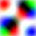
Changes the general rendering composition mode (compliant with SVG). This method applies only to the TBitmap surfaces with Alpha channel present (pf32bit).Parameters m : TAggBlendMode [*]Example if VG.Attach(Image1.Picture.Bitmap ) then begin VG.ClearAll(255 ,255 ,255 ); // Draw basic blue rectangle VG.NoLine; VG.FillColor(0 ,0 ,255 ); VG.Rectangle(50 ,50 ,150 ,150 ); // Rotate coordinates by 45 degrees VG.Translate(-ClientWidth / 2 ,-ClientHeight / 2 ); VG.Rotate (Deg2Rad(45 ) ); VG.Translate(ClientWidth / 2 ,ClientHeight / 2 ); // Changing the general composition mode VG.BlendMode(AGG_BlendContrast ); // Draw the same blue rectangle but with red color // Result comes from applying composition mode VG.FillColor(255 ,0 ,0 ); VG.Rectangle(50 ,50 ,150 ,150 ); end; More complex example:
|
TAgg2D.BlendMode : TAggBlendMode [*] | ||
Description
Retrieves the current general composition mode.Returns Returned is constant identifying the current general composition mode. |
TAgg2D.AntiAliasGamma (g ) | ||
Description
Changes the value of Anti Alias Gamma correction.Parameters g : doubleExample For Gamma correction demo see the example 08 above. |
TAgg2D.FillColor
(c ) TAgg2D.FillColor (r, g, b, a ) |
||
Description
Changes the color used to fill interior of objects being drawn.Parameters c : TAggColor [*]Example if VG.Attach(Image1.Picture.Bitmap ) then begin VG.ClearAll(255 ,255 ,255 ); // Changing fill color to HTML color Gold #FFD700 VG.FillColor($FF ,$D7 ,$00 ); VG.Rectangle(30 ,30 ,180 ,80 ); // Adding Alpha Transparency to previous fill color VG.Translate(0 ,80 ); VG.FillColor($FF ,$D7 ,$00 ,128 ); VG.Rectangle(30 ,30 ,180 ,80 ); end; |
TAgg2D.FillColor : TAggColor [*] | ||
Description
Retrieves the current color used to fill interior of objects being drawn.Returns Returned is Fill color in one data structure (r,g,b,a). |
TAgg2D.LineColor
(c ) TAgg2D.LineColor (r, g, b, a ) |
||
Description
Changes the color used on stroke of objects being drawn.Parameters c : TAggColor [*]Example if VG.Attach(Image1.Picture.Bitmap ) then begin VG.ClearAll(255 ,255 ,255 ); // Changing Line color to HTML color Medium Blue #0000CD VG.LineColor($00 ,$00 ,$CD ); VG.Rectangle(30 ,30 ,180 ,80 ); // Adding Alpha Transparency to previous Line color VG.Translate(0 ,80 ); VG.LineColor($00 ,$00 ,$CD ,128 ); VG.Rectangle(30 ,30 ,180 ,80 ); end; |
TAgg2D.LineColor : TAggColor [*] | ||
Description
Retrieves the current color used on stroke of objects being drawn.Returns Returned is Line color in one data structure (r,g,b,a). |
TAgg2D.FillLinearGradient (x1, y1, x2, y2, c1, c2, profile ) | ||
Description
Linear fill gradient increases linearly along the line from starting to ending point and it is constant along perpendicular lines.Parameters x1 : doubleExample if VG.Attach(Image1.Picture.Bitmap ) then begin VG.ClearAll(255 ,255 ,255 ); // Gradient colors - from Red to Yellow c1.Construct(255 ,0 ,0 ); c2.Construct(255 ,255 ,0 ); // Gradient proceeds from Top Left corner (10:10) // to the Bottom Right corner // (ClientWidth - 10:ClientHeight - 10) VG.FillLinearGradient( 10 ,10 , ClientWidth - 10 , ClientHeight - 10 , c1 ,c2 ,0.9 ); // Gradient appears as a filling of objects // consequently being drawn VG.Rectangle( 10 ,10 , ClientWidth - 10 , ClientHeight - 10 ); end; Remarks One important note about gradients in TAgg2D is that gradients are defined per surface and not per rendering object. Gradient location and dimensions relates to origin of surface and coordinates transformations transform also gradients definition. So after setup of one gradient (for fill or stroke) a series of drawing shapes will render across the last defined gradient. |
TAgg2D.LineLinearGradient (x1, y1, x2, y2, c1, c2, profile ) | ||
Description
Linear line gradient increases linearly along the line from starting to ending point and it is constant along perpendicular lines.Parameters x1 : doubleExample if VG.Attach(Image1.Picture.Bitmap ) then begin VG.ClearAll(255 ,255 ,255 ); // Turn off filling & Set wide stroke VG.NoFill; VG.LineWidth(20 ); // Gradient colors // from DeepSkyBlue #00BFFF - DarkRed #8B0000 c1.Construct($00 ,$BF ,$FF ); c2.Construct($8B ,$00 ,$00 ); // Gradient proceeds from Top Left corner (20:20) // to the Bottom Right corner // (ClientWidth - 20:ClientHeight - 20) VG.LineLinearGradient( 20 ,20 , ClientWidth - 20 , ClientHeight - 20 , c1 ,c2 ,0.9 ); // Gradient appears as a filling of objects stroke VG.Rectangle( 20 ,20 , ClientWidth - 20 , ClientHeight - 20 ); end; |
TAgg2D.FillRadialGradient (x, y, r, c1, c2, profile ) | ||
Description
Radial fill gradient produces equally proportioned circles of colors increasing from the origin to the outer bound.Parameters x : doubleExample if VG.Attach(Image1.Picture.Bitmap ) then begin VG.ClearAll(255 ,255 ,255 ); // Gradient colors // from DeepSkyBlue #00BFFF - Red #FF0000 c1.Construct($00 ,$BF ,$FF ); c2.Construct($FF ,$00 ,$00 ); // Gradient proceeds from center point // (ClientWidth / 2:ClientHeight / 2 ) // with extent of (ClientWidth - 30 ) / 2 VG.FillRadialGradient( ClientWidth / 2 ,ClientHeight / 2 , (ClientWidth - 30 ) / 2 , c1 ,c2 ,1.0 ); // Gradient appears as a filling of objects being drawn VG.Ellipse( ClientWidth / 2 ,ClientHeight / 2 , (ClientWidth - 30 ) / 2 , (ClientWidth - 30 ) / 2 ); end; |
TAgg2D.LineRadialGradient (x, y, r, c1, c2, profile ) | ||
Description
Radial line gradient produces equally proportioned circles of colors increasing from the origin to the outer bound.Parameters x : doubleExample if VG.Attach(Image1.Picture.Bitmap ) then begin VG.ClearAll(255 ,255 ,255 ); // Turn off fill & set bold line VG.NoFill; VG.LineWidth(15 ); // Gradient colors from Red to Blue c1.Construct($FF ,$00 ,$00 ); c2.Construct($00 ,$00 ,$FF ); // Gradient proceeds from center point // (ClientWidth / 2:ClientHeight / 2 ) // with extent of (ClientWidth + 70 ) / 2 // Concentration profile of 0.2 helps // to place gradient on the stroke of circle VG.LineRadialGradient( ClientWidth / 2 ,ClientHeight / 2 , (ClientWidth + 70 ) / 2 , c1 ,c2 ,0.2 ); // Circle VG.Ellipse( ClientWidth / 2 ,ClientHeight / 2 , (ClientWidth - 80 ) / 2 , (ClientWidth - 80 ) / 2 ); end; |
TAgg2D.FillRadialGradient (x, y, r, c1, c2, c3 ) | ||
Description
Radial fill gradient produces equally proportioned circles of colors increasing from the origin to the outer bound.Parameters x : doubleExample if VG.Attach(Image1.Picture.Bitmap ) then begin VG.ClearAll(255 ,255 ,255 ); // Gradient colors Blue - Green - Red c1.Construct($00 ,$00 ,$FF ); c2.Construct($00 ,$FF ,$00 ); c3.Construct($FF ,$00 ,$00 ); // Gradient proceeds from center point // (ClientWidth / 2:ClientHeight / 2 ) // with extent of (ClientWidth - 30 ) / 2 VG.FillRadialGradient( ClientWidth / 2 ,ClientHeight / 2 , (ClientWidth - 30 ) / 2 , c1 ,c2 ,c3 ); // Circle VG.Ellipse( ClientWidth / 2 ,ClientHeight / 2 , (ClientWidth - 30 ) / 2 , (ClientWidth - 30 ) / 2 ); end; |
TAgg2D.LineRadialGradient (x, y, r, c1, c2, c3 ) | ||
Description
Radial line gradient produces equally proportioned circles of colors increasing from the origin to the outer bound.Parameters x : doubleExample if VG.Attach(Image1.Picture.Bitmap ) then begin VG.ClearAll(255 ,255 ,255 ); // Turn fill off & set bold line VG.NoFill; VG.LineWidth(15 ); // Gradient colors Blue - Green - Red c1.Construct($00 ,$00 ,$FF ); c2.Construct($00 ,$FF ,$00 ); c3.Construct($FF ,$00 ,$00 ); // Gradient proceeds from center point // (ClientWidth / 2:ClientHeight / 2 ) // with extent of (ClientWidth - 30 ) / 2 VG.LineRadialGradient( ClientWidth / 2 ,ClientHeight / 2 , (ClientWidth - 30 ) / 2 , c1 ,c2 ,c3 ); // Cross lines VG.Line( 10 ,ClientHeight / 2 , ClientWidth - 10 ,ClientHeight / 2 ); VG.Line( ClientWidth / 2 ,10 , ClientWidth / 2 ,ClientHeight - 10 ); // Rotate +45 degrees VG.Translate(-ClientWidth / 2 ,-ClientHeight / 2 ); VG.Rotate (Deg2Rad(45 ) ); VG.Translate(ClientWidth / 2 ,ClientHeight / 2 ); // Same cross lines VG.Line( 10 ,ClientHeight / 2 , ClientWidth - 10 ,ClientHeight / 2 ); VG.Line( ClientWidth / 2 ,10 , ClientWidth / 2 ,ClientHeight - 10 ); end; |
TAgg2D.LineWidth : double | ||
Description
Retrieves the current width of line.Returns Returned is the width of strokes (lines) [in subpixels]. |
TAgg2D.LineCap (cap ) | ||
Description
Changes the current type of stroke (line) ending.Parameters cap : TAggLineCap [*]Example if VG.Attach(Image1.Picture.Bitmap ) then begin VG.ClearAll(255 ,255 ,255 ); // Bold line VG.LineWidth(30 ); // Default AGG_CapRound VG.Line(40 ,40 ,180 ,40 ); // Change to AGG_CapSquare VG.LineCap (AGG_CapSquare ); VG.Translate(0 ,55 ); VG.Line(40 ,40 ,180 ,40 ); // Change to AGG_CapButt VG.LineCap (AGG_CapButt ); VG.Translate(0 ,55 ); VG.Line(40 ,40 ,180 ,40 ); end; |
TAgg2D.LineCap : TAggLineCap [*] | ||
Description
Retrieves the current type of line (stroke) cap.Returns Returned is constant specifying the current type of line (stroke) cap. |
TAgg2D.LineJoin (join ) | ||
Description
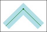
Changes the current type of bending on corners of stroke (line).Parameters join : TAggLineJoin [*]Example if VG.Attach(Image1.Picture.Bitmap ) then begin VG.ClearAll(255 ,255 ,255 ); // Bold line & drawing path VG.LineWidth(25 ); VG.ResetPath; VG.MoveTo(30 ,90 ); VG.LineTo(90 ,30 ); VG.LineTo(150 ,90 ); // Default AGG_JoinRound VG.Translate(10 ,-10 ); VG.DrawPath(AGG_StrokeOnly ); // Change to AGG_JoinMiter VG.LineJoin (AGG_JoinMiter ); VG.Translate(0 ,50 ); VG.DrawPath (AGG_StrokeOnly ); // Change to AGG_JoinBevel VG.LineJoin (AGG_JoinBevel ); VG.Translate(0 ,50 ); VG.DrawPath (AGG_StrokeOnly ); end; |
TAgg2D.LineJoin : TAggLineJoin [*] | ||
Description
Retrieves the current type of bending on corners of stroke (line).Returns Returned is constant specifying the current type of bending on corners of stroke (line). |
TAgg2D.FillEvenOdd : boolean | ||
Description
Retrieves the current state of rasterizer's filling rule.Returns If True, rasterizer's rule is Even/Odd. |
TAgg2D.Transformations : TAggTransformations [*] | ||
Description
Retrieves the currently used affine transformations matrix.Returns Returned is data structure containing currently used affine transformations matrix.Example var af : TAggTransformations; if VG.Attach(Image1.Picture.Bitmap ) then begin VG.ClearAll(255 ,255 ,255 ); // Transform coordinates VG.Translate(10 ,10 ); VG.Scale (2 ,2 ); // Retrieve matrix containing transformations af:=VG.Transformations; // af.affineMatrix is now 2,0,0,2,20,20 end; |
TAgg2D.Viewport (worldX1, worldY1, worldX2, wordlY2, screenX1, screenY1, screenX2, screenY2, opt ) |
||
Description
Transforms source coordinates system rectangle into the destination coordinates system rectangle. Viewport transformation includes translation and scaling in one step. Viewport may change orientations, ratios, angles and distances. If the scaling part of transformation is uniform, orientations, ratios and angles are preserved.Parameters worldX1 : doubleExample if VG.Attach(Image1.Picture.Bitmap ) then begin VG.ClearAll(255 ,255 ,255 ); VG.NoFill; VG.LineWidth(10 ); // First rectangle VG.Rectangle(0 ,0 ,ClientWidth ,ClientHeight ); // Set viewport to the rectangle in middle VG.Viewport( 0 ,0 ,ClientWidth ,ClientHeight , 50 ,50 ,170 ,170 , AGG_XMidYMid ); // The same rectangle in a new viewport coordinates VG.LineColor($FF ,$00 ,$00 ); VG.Rectangle(0 ,0 ,ClientWidth ,ClientHeight ); // This blue triangle would be drawn in some parts // offscreen in original coordinates system VG.LineColor($00 ,$00 ,$FF ); VG.Triangle (100 ,-50 ,-50 ,140 ,ClientWidth + 50 ,140 ); end; Remarks
if VG.Attach(Image1.Picture.Bitmap ) then begin VG.ClearAll(255 ,255 ,255 ); VG.NoFill; VG.LineWidth(10 ); // First rectangle VG.Rectangle(0 ,0 ,ClientWidth ,ClientHeight ); // Set viewport to the rectangle in middle VG.Viewport( 0 ,0 ,ClientWidth ,ClientHeight , 50 ,50 ,170 ,170 , AGG_XMidYMid ); // [!] Applying clipbox on same rectangle as the destination // rectangle, to achieve a true Viewport-like effect VG.ClipBox(50 ,50 ,170 ,170 ); // The same rectangle in a new viewport coordinates VG.LineColor($FF ,$00 ,$00 ); VG.Rectangle(0 ,0 ,ClientWidth ,ClientHeight ); // This blue triangle is cropped in some parts // in the same way, as if it would be offscreen // in original coordinates system VG.LineColor($00 ,$00 ,$FF ); VG.Triangle (100 ,-50 ,-50 ,140 ,ClientWidth + 50 ,140 ); end; |
TAgg2D.Font (fileName, height, bold, italic, cache, angle ) | ||
Description
Changes the current font to be used for text rendering.Parameters fileName : AnsiStringExample if VG.Attach(Image1.Picture.Bitmap ) then begin VG.ClearAll(255 ,255 ,255 ); // Draw different text variations VG.LineColor($1E ,$90 ,$FF ); VG.FillColor($1E ,$90 ,$FF ); VG.Font( 'Times New Roman' ,25 ,false ,false , AGG_VectorFontCache ,Deg2Rad(270 ) ); VG.Text(200 ,210 ,'Times New Roman' ); VG.LineColor($00 ,$00 ,$CD ); VG.FillColor($00 ,$00 ,$CD ); VG.Font( 'Arial' ,25 ,false ,true , AGG_VectorFontCache ,Deg2Rad(315 ) ); VG.Text(220 ,210 ,'Arial Italic' ); VG.LineColor($6A ,$5A ,$CD ); VG.FillColor($6A ,$5A ,$CD ); VG.Font( 'Courier' ,25 ,true ,false , AGG_RasterFontCache ); VG.Text(220 ,230 ,'Courier Bold Raster' ); VG.LineColor($20 ,$B2 ,$AA ); VG.FillColor($20 ,$B2 ,$AA ); VG.Font( 'Verdana' ,25 ,false ,false , AGG_VectorFontCache ,Deg2Rad(45 ) ); VG.Text(205 ,245 ,'Verdana' ); VG.LineColor($2E ,$8B ,$57 ); VG.FillColor($2E ,$8B ,$57 ); VG.Font( 'Tahoma' ,25 ,false ,false , AGG_VectorFontCache ,Deg2Rad(90 ) ); VG.Text(185 ,250 ,'Tahoma' ); VG.LineColor($B8 ,$86 ,$0B ); VG.FillColor($B8 ,$86 ,$0B ); VG.Font( 'Lucida Console' ,25 ,true ,false , AGG_VectorFontCache ,Deg2Rad(135 ) ); VG.Text(165 ,240 ,'Lucida Console' ); VG.NoLine; VG.FillColor($FF ,$00 ,$00 ); VG.Font( 'Galleria' ,20 ,true ,false , AGG_VectorFontCache ,Deg2Rad(180 ) ); VG.Text(160 ,220 ,'Galleria' ); VG.FillColor($FF ,$A5 ,$00 ); VG.Font( 'Briquet' ,30 ,false ,true , AGG_VectorFontCache ,Deg2Rad(225 ) ); VG.Text(170 ,200 ,'Briquet Italic' ); end; |
TAgg2D.TextAlignment (alignX, alignY ) | ||
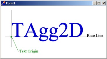
Description
Changes the type of horizontal and vertical alignment around the Text Origin.Parameters alignX : TAggTextAlignment [*]Example if VG.Attach(Image1.Picture.Bitmap ) then begin VG.ClearAll(255 ,255 ,255 ); // Some prior positioning VG.Scale (0.7 ,0.7 ); VG.Translate(-10 ,-70 ); // Text Alignment leading lines VG.LineColor($A9 ,$A9 ,$A9 ); VG.Line(250.5 - 150 ,150.5 ,250.5 + 150 ,150.5 ); VG.Line(250.5 ,150.5 - 20 ,250.5 ,150.5 + 20 ); VG.Line(250.5 - 150 ,200.5 ,250.5 + 150 ,200.5 ); VG.Line(250.5 ,200.5 - 20 ,250.5 ,200.5 + 20 ); VG.Line(250.5 - 150 ,250.5 ,250.5 + 150 ,250.5 ); VG.Line(250.5 ,250.5 - 20 ,250.5 ,250.5 + 20 ); VG.Line(250.5 - 150 ,300.5 ,250.5 + 150 ,300.5 ); VG.Line(250.5 ,300.5 - 20 ,250.5 ,300.5 + 20 ); VG.Line(250.5 - 150 ,350.5 ,250.5 + 150 ,350.5 ); VG.Line(250.5 ,350.5 - 20 ,250.5 ,350.5 + 20 ); VG.Line(250.5 - 150 ,400.5 ,250.5 + 150 ,400.5 ); VG.Line(250.5 ,400.5 - 20 ,250.5 ,400.5 + 20 ); VG.Line(250.5 - 150 ,450.5 ,250.5 + 150 ,450.5 ); VG.Line(250.5 ,450.5 - 20 ,250.5 ,450.5 + 20 ); VG.Line(250.5 - 150 ,500.5 ,250.5 + 150 ,500.5 ); VG.Line(250.5 ,500.5 - 20 ,250.5 ,500.5 + 20 ); VG.Line(250.5 - 150 ,550.5 ,250.5 + 150 ,550.5 ); VG.Line(250.5 ,550.5 - 20 ,250.5 ,550.5 + 20 ); // Font & Colors VG.FillColor($00 ,$00 ,$8B ); VG.NoLine; VG.TextHints(false ); VG.Font( 'Times New Roman' ,40.0 , false ,false ,AGG_VectorFontCache ); // All Text Alignment Cases VG.TextAlignment(AGG_AlignLeft ,AGG_AlignBottom ); VG.Text(250.0 ,150.0 ,'Left-Bottom' ,true ,0 ,0 ); VG.TextAlignment(AGG_AlignCenter ,AGG_AlignBottom ); VG.Text(250.0 ,200.0 ,'Center-Bottom' ,true ,0 ,0 ); VG.TextAlignment(AGG_AlignRight ,AGG_AlignBottom ); VG.Text(250.0 ,250.0 ,'Right-Bottom' ,true ,0 ,0 ); VG.TextAlignment(AGG_AlignLeft ,AGG_AlignCenter ); VG.Text(250.0 ,300.0 ,'Left-Center' ,true ,0 ,0 ); VG.TextAlignment(AGG_AlignCenter ,AGG_AlignCenter ); VG.Text(250.0 ,350.0 ,'Center-Center' ,true ,0 ,0 ); VG.TextAlignment(AGG_AlignRight ,AGG_AlignCenter ); VG.Text(250.0 ,400.0 ,'Right-Center' ,true ,0 ,0 ); VG.TextAlignment(AGG_AlignLeft ,AGG_AlignTop ); VG.Text(250.0 ,450.0 ,'Left-Top' ,true ,0 ,0 ); VG.TextAlignment(AGG_AlignCenter ,AGG_AlignTop ); VG.Text(250.0 ,500.0 ,'Center-Top' ,true ,0 ,0 ); VG.TextAlignment(AGG_AlignRight ,AGG_AlignTop ); VG.Text(250.0 ,550.0 ,'Right-Top' ,true ,0 ,0 ); end; |
TAgg2D.TextHints (hints ) | ||
Description
Changes the status of text hinting for the current font.Parameters hints : booleanExample Try to play with following example. Checking and unchecking the "Hinting" checkbox changes the grid fitting on the fly, so you can see how hinter influences the resulting shape of glyphs. Also resizing the form proportionally zooms the text. |
TAgg2D.AddEllipse (cx, cy, rx, ry, dir ) | ||
Description
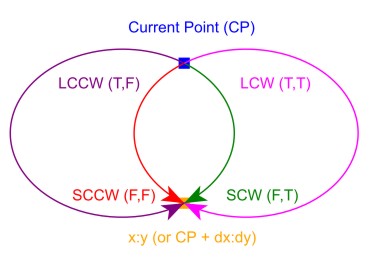
Adds a new closed subpath comprising of a complete ellipse at defined coordinates with defined horizontal and vertical radius. Previous subpath is leaved as is, closed or open.Parameters cx : doubleExample if VG.Attach(Image1.Picture.Bitmap ) then begin VG.ClearAll (255 ,255 ,255 ); VG.FillColor($FF ,$00 ,$00 ); // First subpath comprising of a single line VG.MoveTo(10 ,10 ); VG.LineTo(50 ,50 ); // Add an Ellipse closed subpath to the path VG.AddEllipse(100 ,80 ,80 ,50 ,AGG_CW ); // Second single line from new Current Point // starting at 3 hours of ellipse's perimeter VG.LineTo(200 ,150 ); // Render path VG.DrawPath(AGG_FillAndStroke ); end; |
TAgg2D.DrawPath (flag ) | ||
Description
Draws a path defined with path commands in one pass, using the selected drawing mode.Parameters flag : TAggDrawPathFlag [*] = AGG_FillAndStrokeExample if VG.Attach(Image1.Picture.Bitmap ) then begin VG.ClearAll(255 ,255 ,255 ); // 3/4 Red Pie VG.ResetPath; VG.FillColor(255 ,0 ,0 ,100 ); VG.LineColor(0 ,0 ,255 ,100 ); VG.LineWidth (2 ); VG.MoveTo(300 / 2 ,200 / 2 ); VG.HorLineRel(-150 / 2 ); VG.ArcRel( 150 / 2 ,150 / 2 ,0 , true ,false ,150 / 2 ,-150 / 2 ); VG.ClosePolygon; // Draw path in various rendering modes VG.Translate(-50 ,0 ); VG.DrawPath (AGG_FillAndStroke ); VG.Translate(120 ,0 ); VG.DrawPath (AGG_FillOnly ); VG.Translate(120 ,0 ); VG.DrawPath (AGG_StrokeOnly ); VG.Translate(120 ,0 ); VG.DrawPath (AGG_FillWithLineColor ); end; |
TAgg2D.ImageFilter (f ) | ||
Description
Changes the current type of resampling method for images (TBitmap and descendants).Parameters f : TAggImageFilter [*] |
TAgg2D.ImageFilter : TAggImageFilter [*] | ||
Description
Retrieves the current type of resampling method for images (TBitmap and descendants).Returns Returned is a constant defining the type of resampling method for images. |
TAgg2D.ImageResample (f ) | ||
Description
Changes the current type of event for image resampling.Parameters f : TAggImageResample [*] |
TAgg2D.ImageResample : TAggImageResample [*] | ||
Description
Retrieves the current type of event for image resampling.Returns Returned is a constant defining the type of event for image resampling. |
Rad2Deg (v ) : double | ||
Description
Converts radians to degrees.Parameters v : doubleReturns Returned is a value in degrees. |
TAggRectD | ||
Description
TAggRectD is a data structure used in TAgg2D API to define a subpixel rectangle.Structure
|
TAggDirection | ||
Description
Defines the direction to go when generating an ellipse.Constant Values AGG_CW |
TAggBlendMode | ||
Description
TAggBlendMode determines the compositing operation used, when rendering individual pixels onto the drawing surface.Constant Values AGG_BlendAlpha |
2006 - 2008 © Milan Marusinec alias Milano
|