|
Vector Graphics Engine Initialization
Attach
(bitmap,
flip_y
) : boolean
ClearAll
(c )
ClearAll
(r,
g,
b,
a )
Master Rendering Properties
BlendMode
(m )
BlendMode
: TAggBlendMode [*]
MasterAlpha
(a )
MasterAlpha
: double
AntiAliasGamma
(g )
AntiAliasGamma
: double
NoFill
NoLine
FillColor
(c )
FillColor
(r,
g,
b,
a )
FillColor
: TAggColor [*]
LineColor
(c )
LineColor
(r,
g,
b,
a )
LineColor
: TAggColor [*]
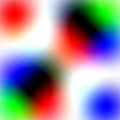
FillLinearGradient
(x1,
y1,
x2,
y2,
c1,
c2,
profile )
LineLinearGradient
(x1,
y1,
x2,
y2,
c1,
c2,
profile )
FillRadialGradient
(x,
y,
r,
c1,
c2,
profile )
LineRadialGradient
(x,
y,
r,
c1,
c2,
profile )
FillRadialGradient
(x,
y,
r,
c1,
c2,
c3 )
LineRadialGradient
(x,
y,
r,
c1,
c2,
c3 )
FillRadialGradient
(x,
y,
r )
LineRadialGradient
(x,
y,
r )
LineWidth
(w )
LineWidth
: double
LineCap
(cap )
LineCap
: TAggLineCap [*]
LineJoin
(join )
LineJoin
: TAggLineJoin [*]
FillEvenOdd
(evenOddFlag )
FillEvenOdd
: boolean
Affine Transformations
Transformations
: TAggTransformations [*]
Transformations
(tr )
ResetTransformations
Affine
(tr )
Rotate
(angle )
Scale
(sx,
sy )
Skew
(sx,
sy )
Translate
(x,
y )
Parallelogram
(x1,
y1,
x2,
y2,
para )
Viewport
(worldX1,
worldY1,
worldX2,
wordlY2,
screenX1,
screenY1,
screenX2,
screenY2,
opt )
Coordinates Conversions
WorldToScreen
(x,
y )
ScreenToWorld
(x,
y )
WorldToScreen
(scalar )
: double
ScreenToWorld
(x,
y )
AlignPoint
(x,
y )
Clipping
ClipBox
(x1,
y1,
x2,
y2 )
ClipBox
: TAggRectD [*]
ClearClipBox
(c )
ClearClipBox
(r,
g,
b,
a )
InBox
(worldX,
worldY )
: boolean
Basic Shapes
Line
(x1,
y1,
x2,
y2 )
Triangle
(x1,
y1,
x2,
y2,
x3,
y3 )
Rectangle
(x1,
y1,
x2,
y2 )
RoundedRect
(x1,
y1,
x2,
y2,
r )
RoundedRect
(x1,
y1,
x2,
y2,
rx,
ry )
RoundedRect
(x1,
y1,
x2,
y2,
rxBottom,
ryBottom,
rxTop,
ryTop )
Ellipse
(cx,
cy,
rx,
ry )
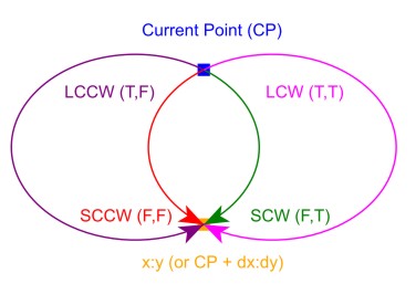
Arc
(cx,
cy,
rx,
ry,
start,
sweep )
Star
(cx,
cy,
r1,
r2,
startAngle,
numRays )
Curve
(x1,
y1,
x2,
y2,
x3,
y3 )
Curve
(x1,
y1,
x2,
y2,
x3,
y3,
x4,
y4 )
Polygon
(xy,
numPoints )
Polyline
(xy,
numPoints )
Path Commands
ResetPath
MoveTo
(x,
y )
MoveRel
(dx,
dy )
LineTo
(x,
y )
LineRel
(dx,
dy )
HorLineTo
(x )
HorLineRel
(dx )
VerLineTo
(y )
VerLineRel
(dy )
ArcTo
(rx,
ry,
angle,
largeArcFlag,
sweepFlag,
x,
y )
ArcRel
(rx,
ry,
angle,
largeArcFlag,
sweepFlag,
dx,
dy )
QuadricCurveTo
(xCtrl,
yCtrl,
xTo,
yTo )
QuadricCurveRel
(dxCtrl,
dyCtrl,
dxTo,
dyTo )
QuadricCurveTo
(xTo,
yTo )
QuadricCurveRel
(dxTo,
dyTo )
CubicCurveTo
(xCtrl1,
yCtrl1,
xCtrl2,
yCtrl2,
xTo,
yTo )
CubicCurveRel
(dxCtrl1,
dyCtrl1,
dxCtrl2,
dyCtrl2,
dxTo,
dyTo )
CubicCurveTo
(xCtrl2,
yCtrl2,
xTo,
yTo )
CubicCurveRel
(dxCtrl2,
dyCtrl2,
dxTo,
dyTo )
AddEllipse
(cx,
cy,
rx,
ry,
dir )
ClosePolygon
DrawPath
(flag )
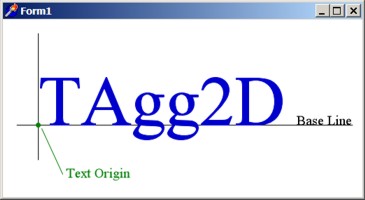
Text Rendering
FlipText
(flip )
Font
(fileName,
height,
bold,
italic,
cache,
angle )
FontHeight
: double
TextAlignment
(alignX,
alignY )
TextHints
: boolean
TextHints
(hints )
TextWidth
(str )
: double
Text
(x,
y,
str,
roundOff,
ddx,
ddy )
Image Rendering
ImageFilter
(f )
ImageFilter
: TAggImageFilter [*]
ImageResample
(f )
ImageResample
: TAggImageResample [*]
TransformImage
(bitmap,
imgX1,
imgY1,
imgX2,
imgY2,
dstX1,
dstY1,
dstX2,
dstY2 )
TransformImage
(bitmap,
dstX1,
dstY1,
dstX2,
dstY2 )
TransformImage
(bitmap,
imgX1,
imgY1,
imgX2,
imgY2,
parallelo )
TransformImage
(bitmap,
parallelo )
TransformImagePath
(bitmap,
imgX1,
imgY1,
imgX2,
imgY2,
dstX1,
dstY1,
dstX2,
dstY2 )
TransformImagePath
(bitmap,
dstX1,
dstY1,
dstX2,
dstY2 )
TransformImagePath
(bitmap,
imgX1,
imgY1,
imgX2,
imgY2,
parallelo )
TransformImagePath
(bitmap,
parallelo )
CopyImage
(bitmap,
imgX1,
imgY1,
imgX2,
imgY2,
dstX,
dstY )
CopyImage
(bitmap,
dstX,
dstY )
Standalone API
Deg2Rad
(v )
: double
Rad2Deg
(v )
: double
Agg2DUsesFreeType
: boolean
BitmapAlphaTransparency
(bitmap,
alpha )
: boolean
API Related Types
TAggColor
TAggRectD
TAggDirection
TAggLineJoin
TAggLineCap
TAggBlendMode
TAggTextAlignment
TAggDrawPathFlag
TAggViewportOption
TAggImageFilter
TAggImageResample
TAggFontCacheType
TAggTransformations
|
|